Version 1 of the watch has been made and documented on my Youtube channel. I’ll still document some additional information on this blog and also writing stuff down is a lot easier and faster than videomaking.
This project began in May 2024, right after doing a few other projects like painting my EVA Unit 1 figure and the Furata pendulum. Work was slow and boring since there was no prototyping to be done on in a semiconductor equipment assembly process. To keep my mind fresh with coding, electronic assembly, and 3D printing, I came up with the idea to make my own smartwatch.
This wasn’t a new concept. There are plenty of video and online posts about making ESP32-based smartwatches, with some having lasers or Bluetooth integration.
But I wanted to take this a step further and make an aesthetic housing. For the past half year, I stepped away from engineering projects to do digital art practice, motivated by the uncertainty I had about an engineering career and inner desire to do something creative.
I thought to myself, “it could be interesting to sketch up some concepts for the watch body and attempt to recreate it.” Follow the industrial design process from ground up but also fulfill the roles between artist and engineer.
Aesthetic was a large focus. I spent all my work breaktime and lunch sketching in my tiny notebook, taking inspiration from vintage CRTs, radios, and watches. My coworkers thought I was weird and a bit of a loner for it.

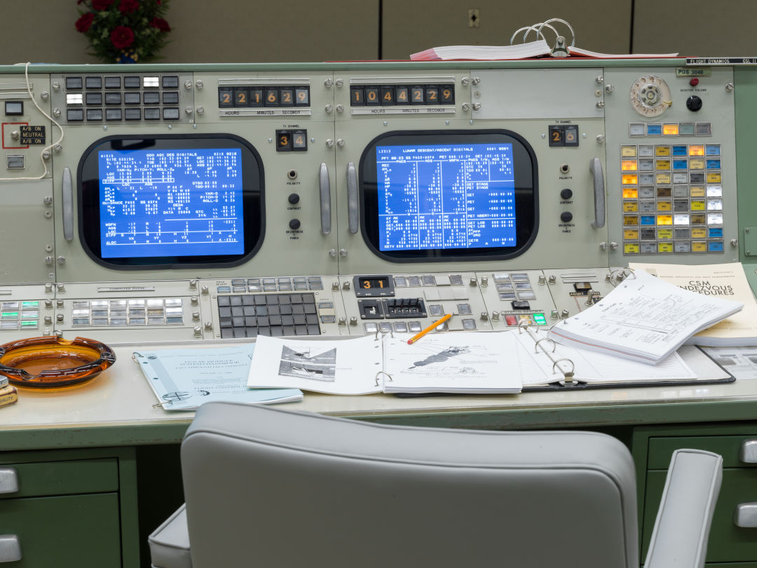
I landed on a design largely inspired by the Apollo Mission Control Room. I recently watched a video by Adam Savage talking about his affinity to objects with history and it resonated with me. Not only could I have a new unique watch I built by hand, I could also infuse some historical appreciation.
After jumping into Fusion360 to whip up a quick model and print, I could then start iterating dimensions to fit the electronics inside.
I had some XIAO-ESP32 C6 chips and IMU chips laying around that I designed around. It would be interesting to incorporate motion tracking into the watch as I have not seen that often in other project.
This was also around the same time as OpenSauce and while I would’ve loved to make a working prototype by then, I had to save it until next year.
The watch face will be rendered on a small OLED screen utilizing the Adafruit GFX library. Instead of uploaded large files consisting of the watch face frames, everything was coded in by functions and redrawn as needed. Working on a tiny screen and making things feel representative of the mission control screens was difficult. Like, how much clearer can you write words 3 pixel high.
It came out quite nice in the end. I did have a big confusion on why my i2C screen didn’t connect and showed a mess of colored noise. I thought it could be a terrible soldering job making DIY header pins out of solid core wire, resulting in octopus looking chips. But nope, thankfully it had to do with the library incompatibility.
Additional tweaks to get the blue color and this is what the screen looks like behind the 3D printed cover.

Cleaned up the screen layout more. Each small text entry will be its own variable this watch is “tracking”, like O2, N, battery, and flux. Or just gibberish symbols so that it looks visually interesting at a glance. Experimented with displaying the time as orange over black as each mission control screen has time projected from a 7 segment display.

History time
Speaking of vintage displays, over the course of this project I have learned way more about display technology back in the 1960s than I expected.
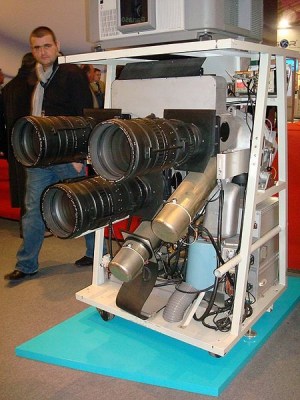
Before the introduction of LEDs, the orange seven segment displays you can see on each console comes from either a projection display, incandescent modules, or Nixie tubes.
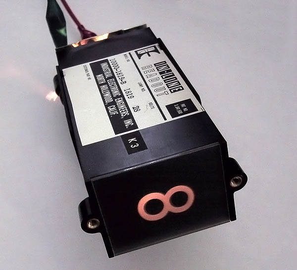
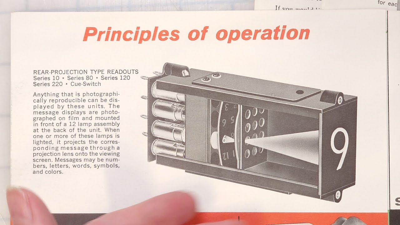
The following model here is a IEE One-Plane projection display (also known as in-line displays), invented in 1956 primarily for use in industrial controls. Each character is projected from a light that shines through a mask of any pattern inscribed into it such as digits or industrial warnings. Chunky but does produce a clean analog image.
For an alternative display, I looked at the trajectory maps on the back wall of the control room. This screen used a static bitmap for the background and clock drawn over. A simple screen with no constantly updating digits like the first screen so I can just refresh the entire display every minute.

History behind those back wall displays! Also like with the CRTs and seven segment displays, these too are projectors. To create large scale projections, eidophor projectors were used that overlayed static images over a moving scribe to draw incoming telemetry data.
This video, like the previous I linked, has a great exploration into the history of these projectors so do take a look!
Also another great read, a hackaday article summarizing a talk about how steam-punky and inconvenient the machine is. Mike Harrison Exposes Hot Oil And High Voltage Of Ancient Live Projector
Housing final
Electronics and code was done or close to the final product. Last step is to finalize the housing dimensions and fit everything together.
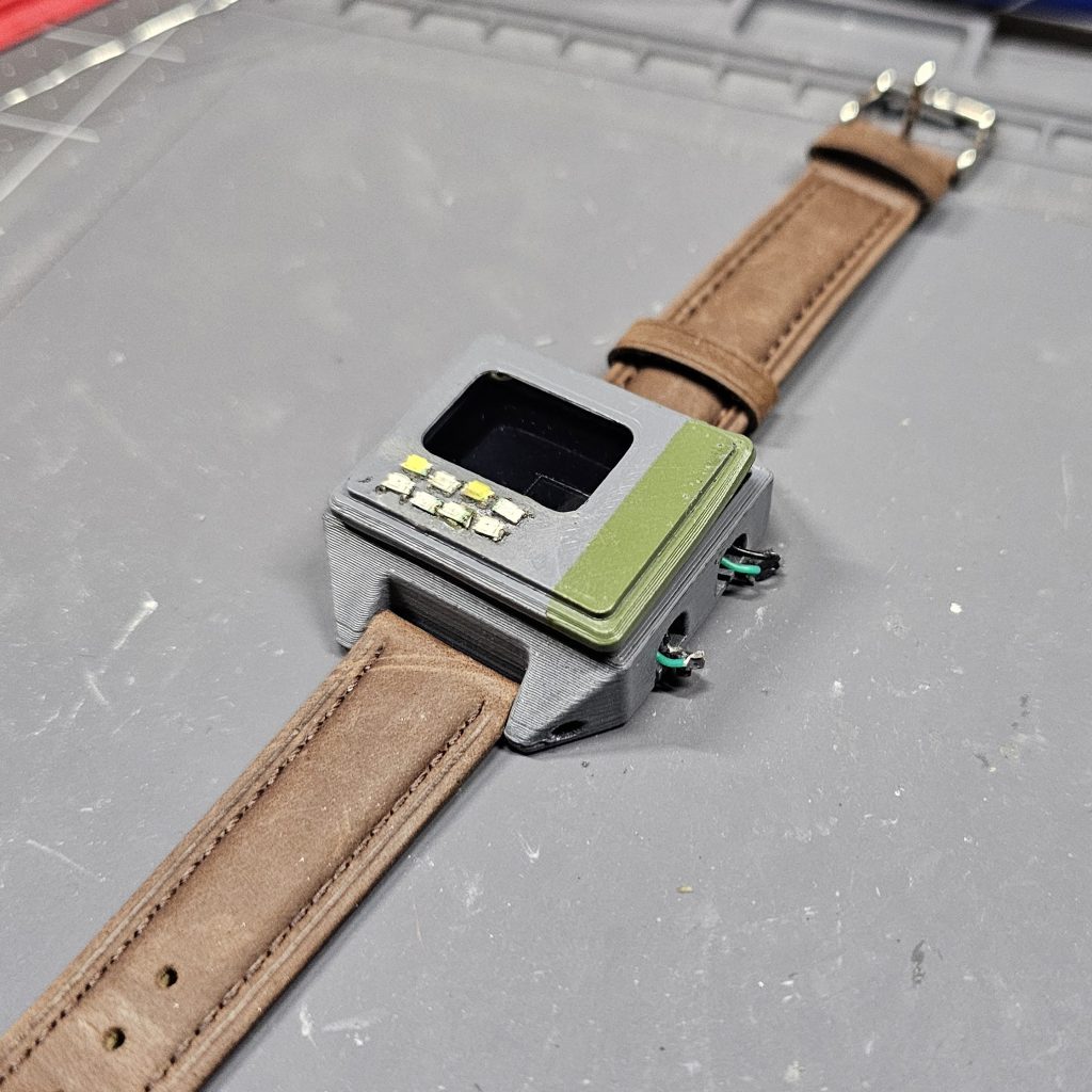
I printed a case with as minimal space for internals as possible to prevent a giant potato being strapped to my wrist. My printer is not as accurate as a resin printer so small details like cutouts for LEDs were added manually with a modelmaker’s chisel.
Each part was spray painted with grey and green accent. The color did not bright or clean at all, especially the green, which fit the industrial controls aesthetic but did look like it was made in a cave.
Wasn’t a big fan of the loose wires so I redid the soldering with solid core, also with the intent that it would its shape as I fit it inside the case.
A MCP23017 GPIO expander chip was added to drive the case LEDs and vibration motor. Future iterations would use a shift register instead.
One issue I encountered when closing up the housing was that after I glued up the housing, the vibration motor wouldn’t work. It worked perfectly fine outside so why does it die so consistently? Turns out, the off-gassing from superglue that I used to attach the front builds up on the motor commutators and gums it up (aka blooming as noticed on the motor’s shell with glue buildup).
Instead of lining the front rim with glue, I just slowly applied it to reduce the fumes coming off. Seems to work just fine
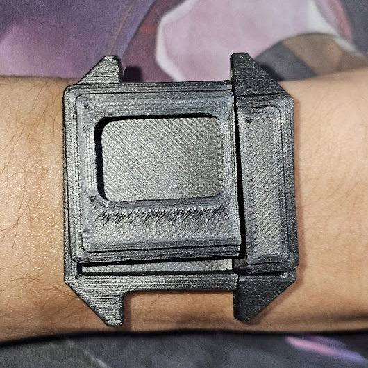
However, with how many times I removed the front cover and applied glue, the aesthetic took a further nose dive. Combined with an impromptu cutout for the esp32c6 USB, now it definitely looks like scraps.
Finally, I had a working prototype I could wear around. The battery life is pretty terrible, around 5hrs, since I never put the ESP32 into deep sleep. The clock also loses count afterwhile and after losing power (which is why I coded a clock calibrate screen), but for the future I would consider a separate RTC clock source.
Some other things I’d improve: either tuning the printer for fine details or hand carving the shell, actually integrating the sensors, add health monitoring, improve battery life with sleep mode, and figure out how to interface it with a network.
But that will have to wait until version 2, complete with a custom PCB.

Leave a comment