
Every 2nd sunday, 6AM to 12PM, of every month March to September, Silicon Valley holds an Electronics Flea Market. I had just recently discovered this event when getting interested in vintage tech and restoration so I marked my calender and waited.
The flea market was held in May 19, 2024 in Saratoga.
My main goal for going to the flea market was to find an oscilloscope. I never owned one before but I have used on in college, so I was aware of how useful it will be once I start doing more electronic repairs. I’ve only been to general flea markets so it was cool to see a specialized, nerdy crowd here. Plenty of old vintage tech of questionable conditions (radios, CRTs, computer parts). This must’ve been near the end of quarter for universities as groups of young adults were walking about talking about EE classes and finals. Man was it good to be back in this kind of environment.
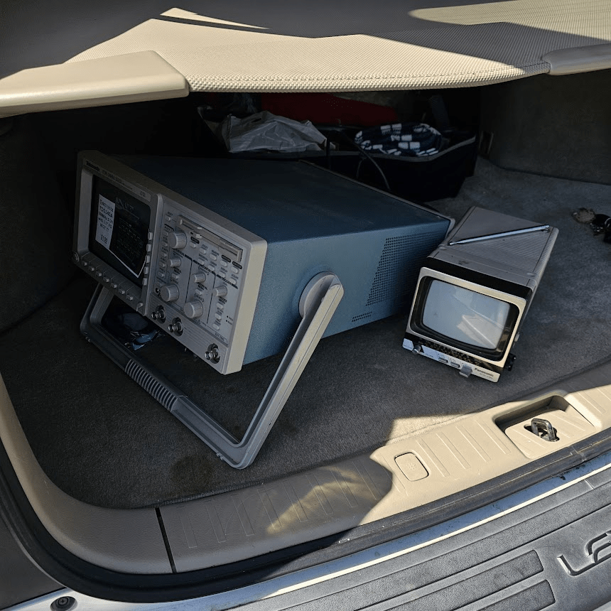
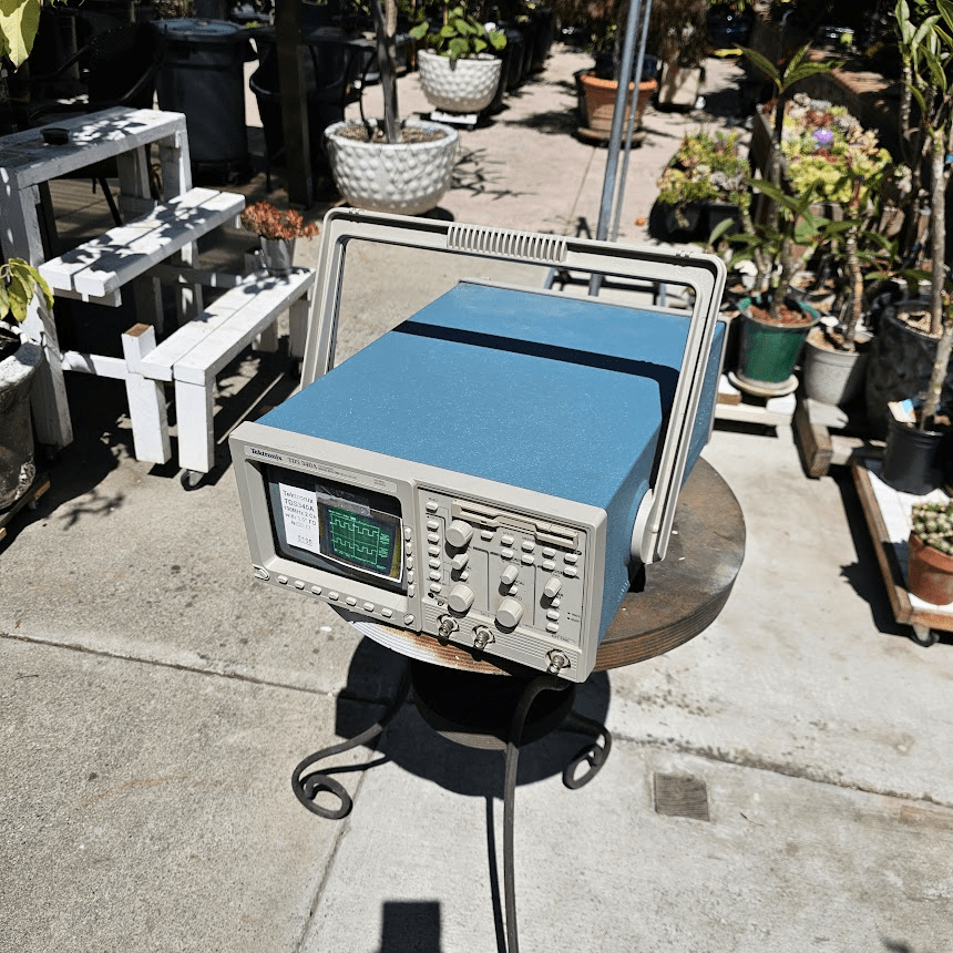
I snagged a Tektronix TDS340A oscilloscope for 100$, a damn good steal. I didn’t have a power supply to test at the market so I blindly trusted the seller when he said it was in full working order. He even threw in a pair of probes for free, how nice!
When walking about, I did catch my eye on a tiny portable radio CRT. The seller had no idea what the condition was and sold it for 25$. Unwise. I bought it anyways. I’m sure I’ll find a use for it.
Back when I was still in my parents house, I dusted it off and powered it on for the first time. It made a nice hum, slow startup. But the seller was right, it was perfectly working. No high pitch CRT whine either.
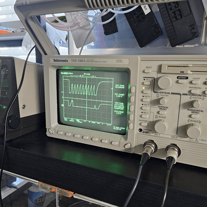
It say perfectly on top of my 3D printer lack enclosure.

This is where I started probing digital in/out signal from an Arduino and i2C signal lines to test the oscilloscope. Nothing beats the analog look.
This will prove extremely useful while I continue my smartwatch project and diagnose communication errors.
After a long stretch of side projects / trips
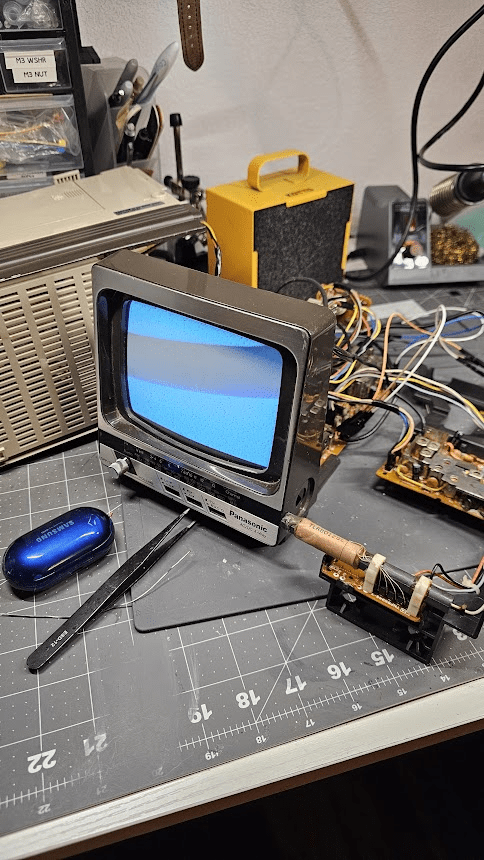
So when I first bought it, I turned on the TV to check what is broken if at all. The radio worked just fine, I could still tune into local stations. The CRT just filled with static noise, which is to be expected since there are no analog tv stations being broadcasted over in the area. If I wanted to turn this into a useable screen, I would need to adapt it to HDMI or run an internal connection.
The TV by the way, was a Panasonic 1985 TRG 511T B&W radio TV.
Its now January 2025. I researched proper CRT discharge safety and opened up the case to see what I’m dealing with.

You see…since I last turned it on last year the screen has completely died. I think I got one last power on before it faded to nothing with only the characteristic high pitch squeal.
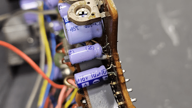
Online forums all recommend checking blown capacitors, so I replaced all of the electrolytic ones. Some definitely failed open and were slightly misshapen or had some kind of crust on it, likely from the internals leaking over the many decades it’s been sitting in a shed.
The screen powered on like before but I still wanted to give it a proper display. White noise static is just not my kind of show.
What I wanted to attempt was to find a way to bypass the radio signal input for the TV and inject my own video signal. To do so, I’d need to figure out what components are on this TV and thankfully there were some service manuals on eBay I could grab that contained schematics. Bless the age of repairable products.
(I’ll need to go back to my old notes and update this blog with specifics on the chip and such)
The TV is split into two distinct circuits, the radio and TV portion, where a slide switch redirects power between the two. The TV portion features multiple chips for processing radio signals but the one I was interested in runs straight from the TV signal processor to the deflection yoke.
I have read other forum posts of people bypassing the signal at this location and cross-referencing the signals going into this chip, I believe a simple video line would be sufficient (the chip performs all the amplification nessecary).
First test, produce a video signal from a microcontroller for testing. A little wonky with wires sticking out the bottom of the board but it did make a visible image. The synchronization was way off for some reason but good proof of concept.

Looking deeper into the schematic, there is actually 2 separate chips that utilize a video signal to match the x/y synchronization. I just injected the signal only to the video amp so just need to back trace a little bit farther.

The CRT is now hooked up to a video RCA cable coming from a HDMI to composite converter. Great! I can hook up my laptop and see if I can drag stuff over.
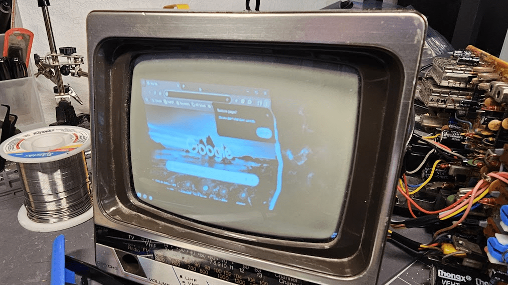
Well, I do see screens on it. Issue, brightness affects deflection. Everything has a weird drunk glasses look to them, especially noticeable for high contrast images. I couldn’t figure out why it would do this?
Future plans
As of October 2025, this CRT has been sitting on my shelf waiting for the answer. I completely forgot about it but I believe my next step is to replace the flyback transformer as that high pitch ringing might be a tell for insufficient power. Maybe the deflection yokes aren’t strong enough to deflect high intensity CRT beams, hence distortion increasing with with brightness.
The screen is too small to be used for anything useful. Maybe a field computer in a pelican box? Or perhaps a visualizer for music? Whatever it’ll be, I’ll be making a follow-up post!

Leave a comment